
Dual Slope ADC

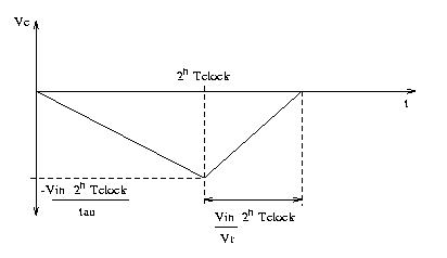
The output of the integrator on the dual slope ADC, Vc, as shown above,
has the same functional form as the integrator output on the voltage to
time and voltage to frequency ADC's, that is:
Vc = (-Vin)t/tau
where tau = RC
Starting with switch S in the Vin position, the capacitor begins to charge as the integration starts. As Vc becomes less than zero and continues to decrease, the comparator output is high, allowing the clock to increment the mod 2n counter. When the MSB switches from one to zero so that the counter is once again all zeros, the flip-flop output goes high, switching S to the -Vr position. Thus Vc begins to increase from its negative value, and when it crosses the zero point, the comparator output goes low, stopping the clock signal from reaching the counter. The counter now shows the number of clocks since S was switched to -Vr. This number is proportional to Vin with proportionality constant 2n/Vr, as shown below.
The time that it took from the beginning of the integration when switch S
was at Vin to when the counter returned to its zero value is
t = 2nTclock
The expression for Vc after S has switched to -Vr is
Vc = -Vin(2n)Tclock/tau + Vr(t' - 2nTclock)/tau
where 2nTclock < t' < 2(2n)Tclock
After S has been at -Vr long enough to make Vc = 0, then the previous
equation becomes:
0 = -Vin(2n)Tclock/tau + Vr(t' - 2nTclock)/tau
t' - 2nTclock = Vin(2n)Tclock/Vr
t' = (Vin/Vr + 1)2nTclock
This is the total time since S was switched to Vin. The time since S was
switched to -Vr is
t' - 2nTclock = Vin(2n)Tclock/Vr
Thus the number of clocks since S was switched to -Vr is
Vin(2n)/Vr which is recorded on the counter.
Notice that the number of clocks since S was switched to -Vr is directly proportional to the input analog voltage Vin, and also that there is no tau in the expression, so this method is the most accurate of the integrating ADC's. The total time for one conversion is (Vin/Vr + 1)2n clocks.