![]()
Exstrom Laboratories
Copyright 2024
Exstrom Laboratories LLC
Steampunk AM Radio for Kids of All Ages
This is an educational AM radio for kids of all ages. Play around with AM radio and learn how it works. A circuit schematic and all the information needed to build one is shown below.
It's got two controls: volume control and tuner. It's designed to be very modular so you can try different things out.
The antenna is a ferrite loop. It's got two coils on it. One coil with 68 turns is tuned by a variable capacitor. It's connected to the capacitor using a terminal block so you can easily slide that coil off and try out coils with different numbers of turns. The other coil has 41 turns. So we've got a 68 turn coil for tuning and a 41 turn coil coupled to it through a ferrite rod.
The signal from the 41 turn coil goes into the AM detector board. This board is based on a TA7642 chip which is in a small TO-92 package with 3 legs, resembling a discrete transistor. It's got an RF amplifier, a detector, and automatic gain control. The coil is connected to this board with a Dupont connector so you can try out coils with different numbers of turns.
The output of the AM detector board goes into the audio amplifier board which is based on an LM386. Both of the boards are connected to a common ground plane. This is important. If you don't have a good ground plane you can get interference, feedback, and the signal won't sound as well if you don't have a good ground. The ground is just connected to one of the batteries.
The detector board runs on 3 volts, the audio amplifier runs on 6 volts, and that's provided by 4 D-cell batteries. It's very low power so these D-cell batteries will basically last forever. And we've got a little 8Ω speaker that's 2 1/4 inches (57 mm) in diameter.
You can do experiments with this radio. The antenna is very directional, so you can tune it to a station, then you can rotate the board until you no longer hear the station. And when you no longer hear it, the ferrite rod will point directly in the direction of the transmitter. You can also try hooking up an external wire antenna. Just take a long wire and wrap it around the ferrite rod, and take the other end and put it on Earth ground, like a plumbing pipe. It has to be an Earth ground, not just the radio circuit ground. This would couple stronger signals into the ferrite loop antenna. You can try picking up long distance AM stations this way.
Video about the radio:
Photos, circuit schematic and other information are shown below. The photos are high resolution, so to see more details, right click an image and open it in a new tab.
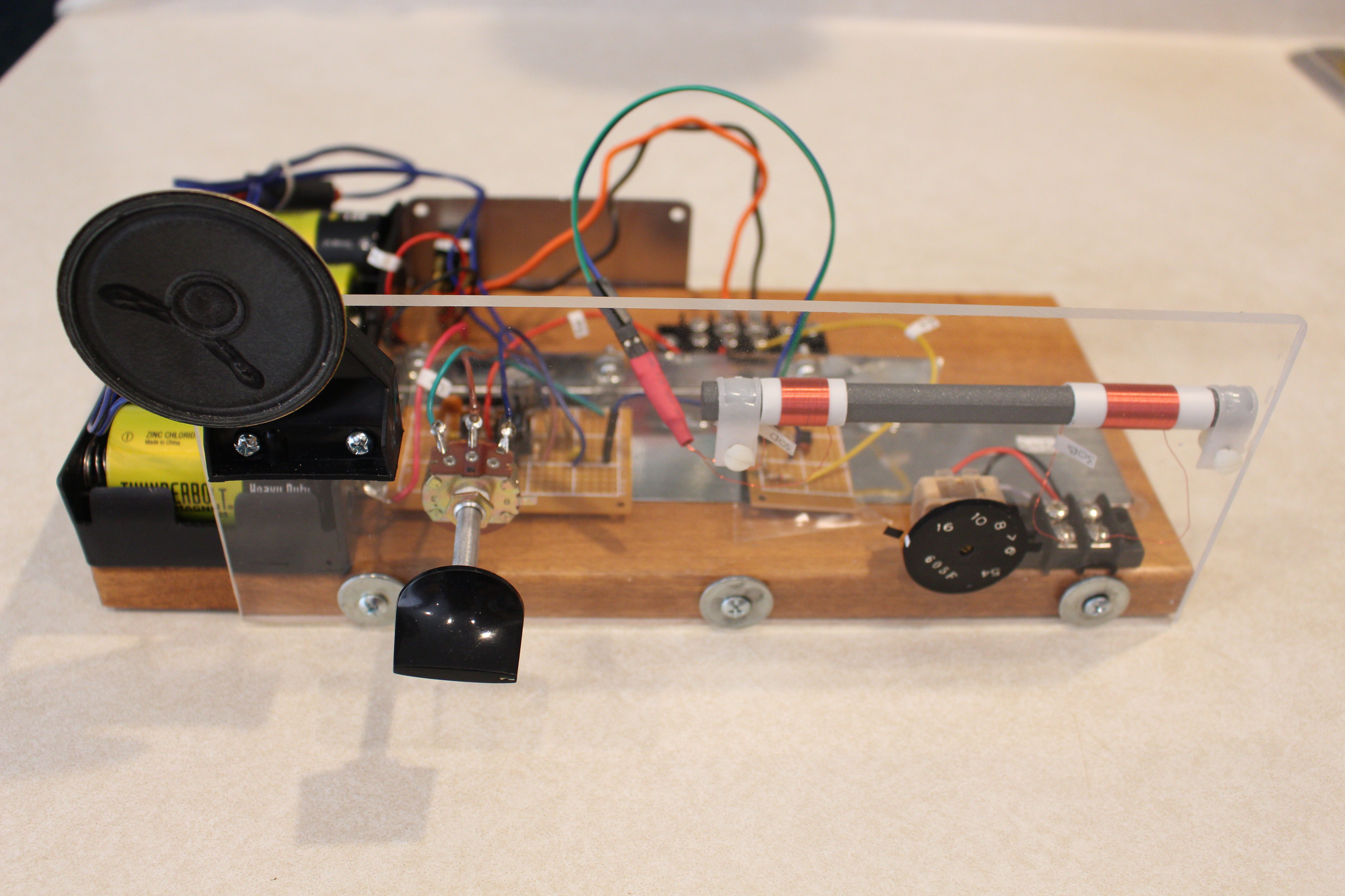
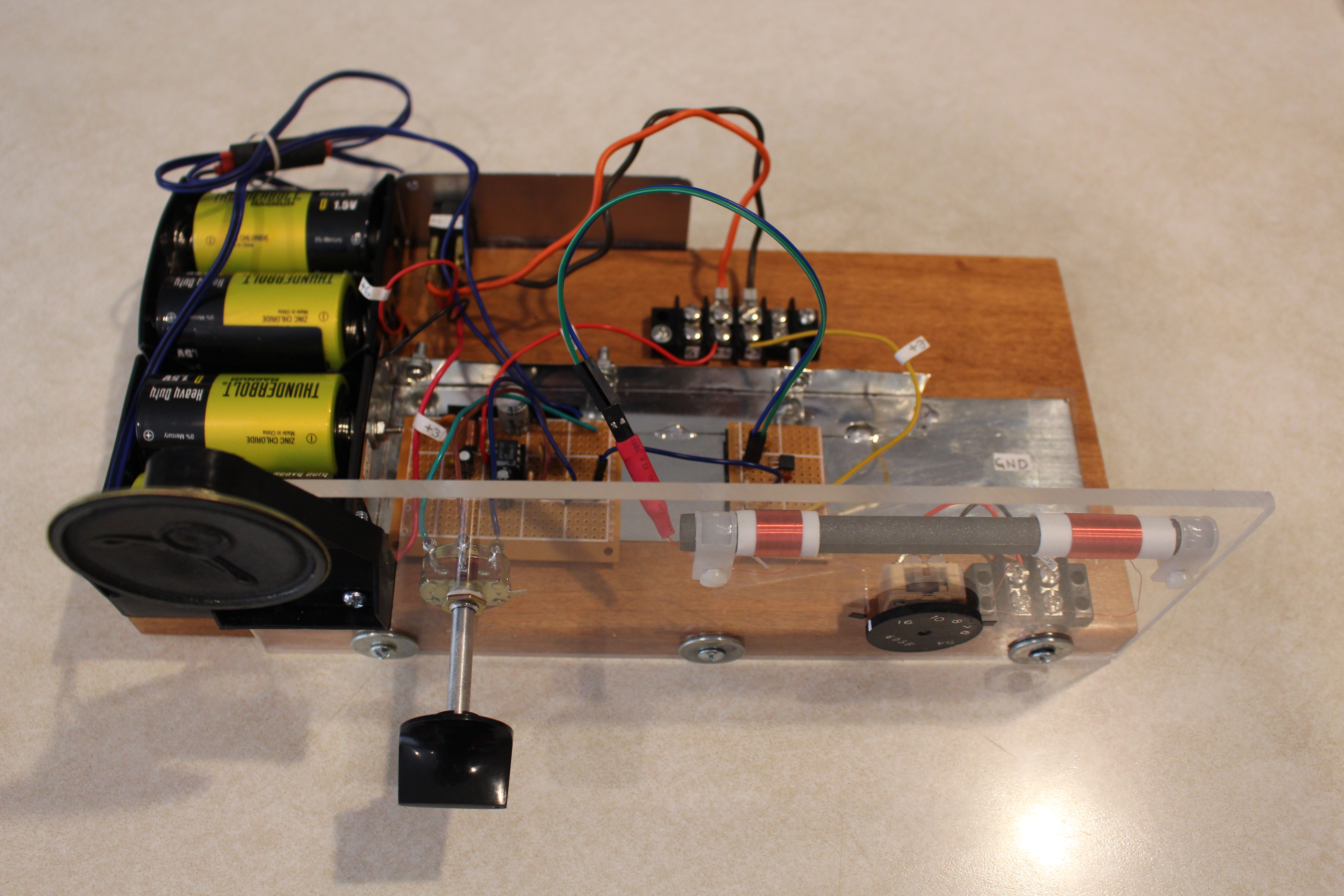
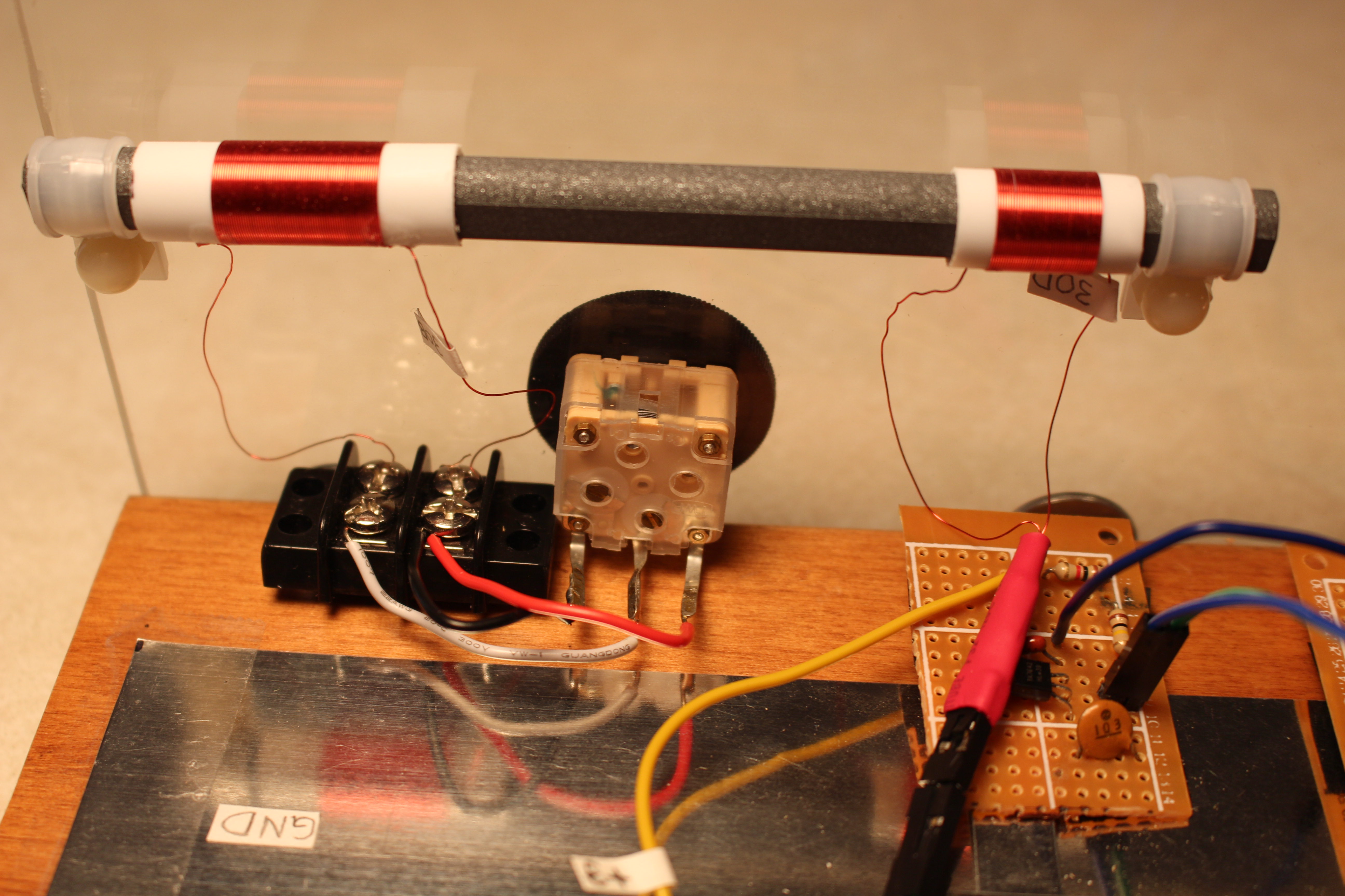 Ferrite loop antenna, variable capacitor, AM detector board and ground plane.
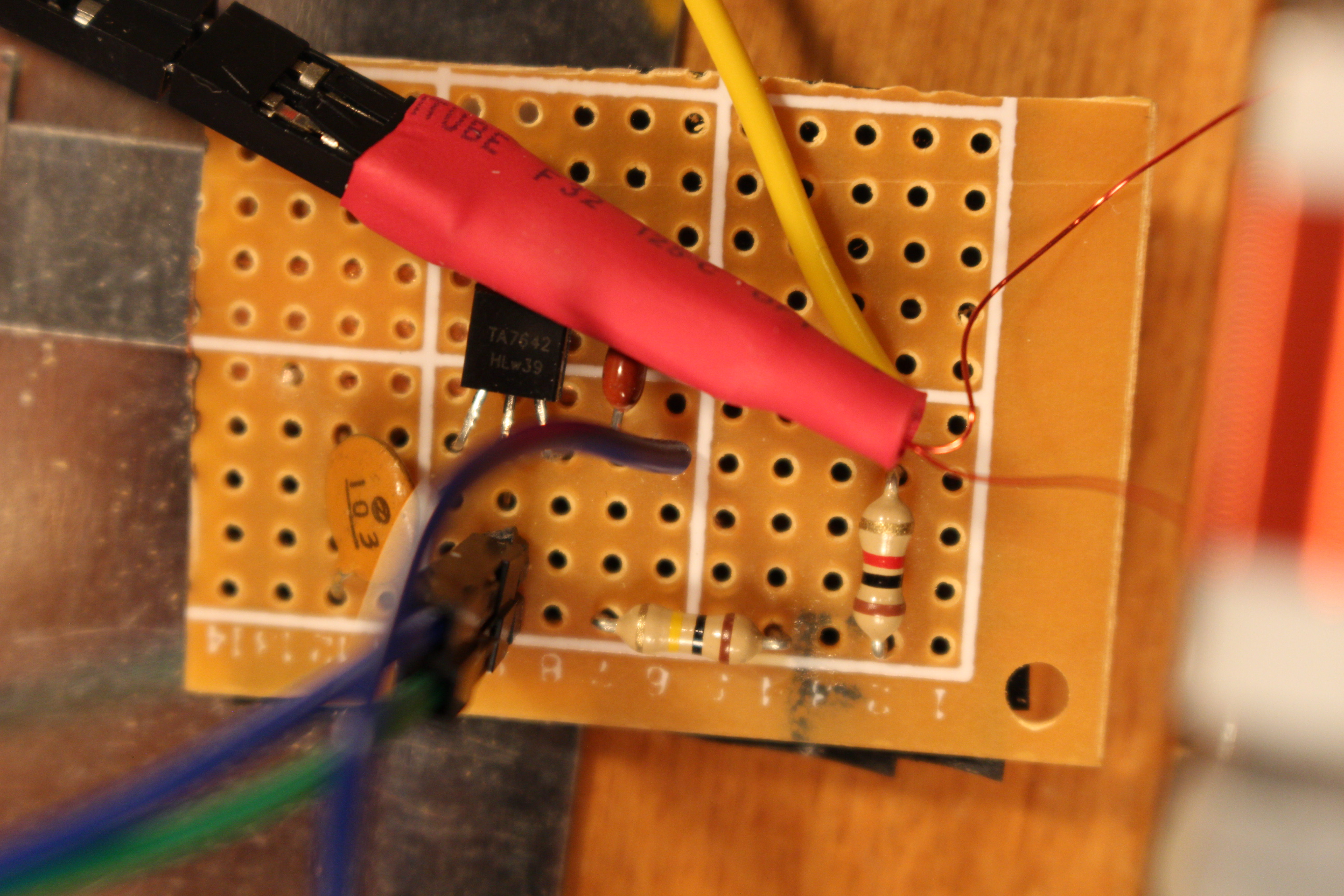 AM detector board
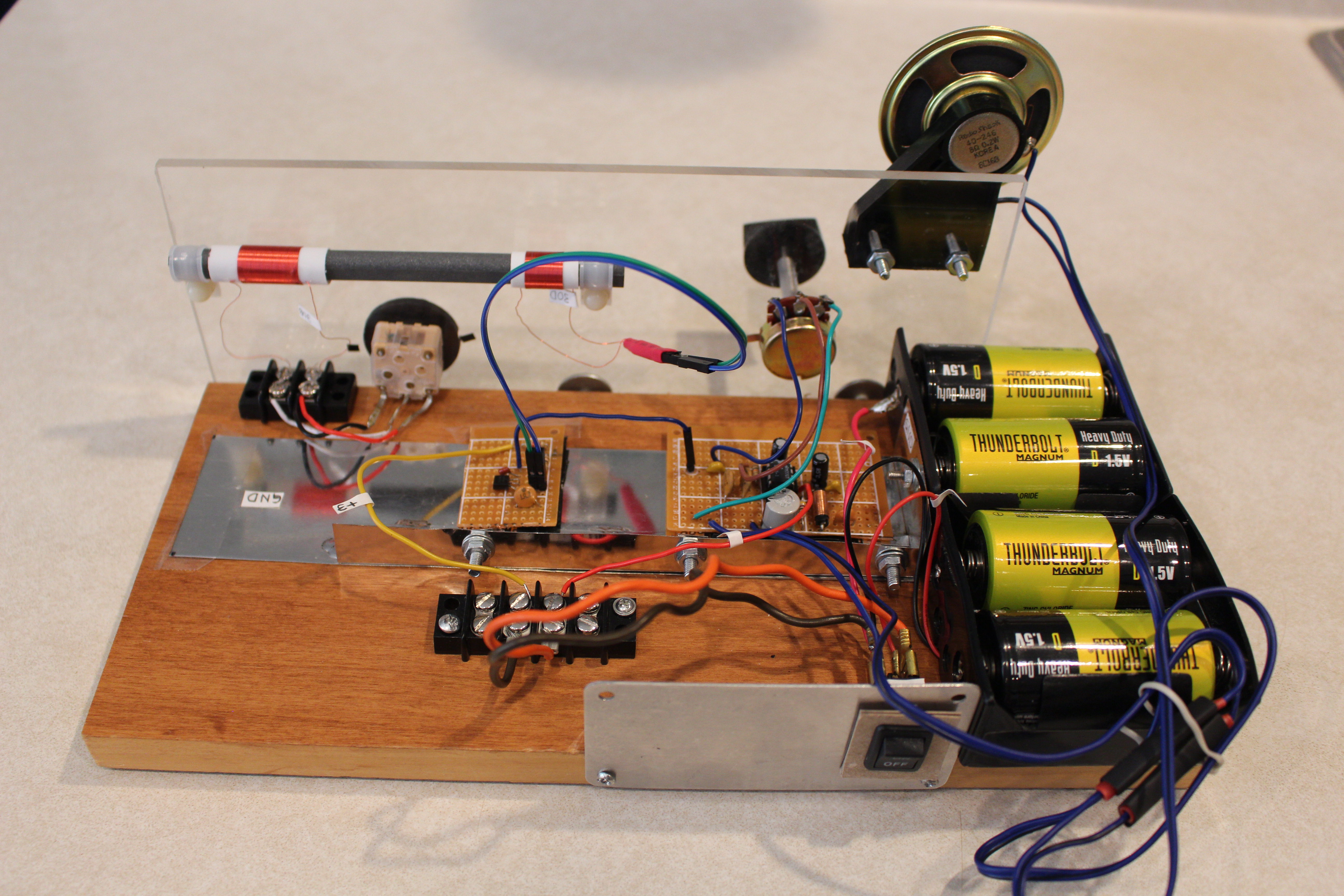
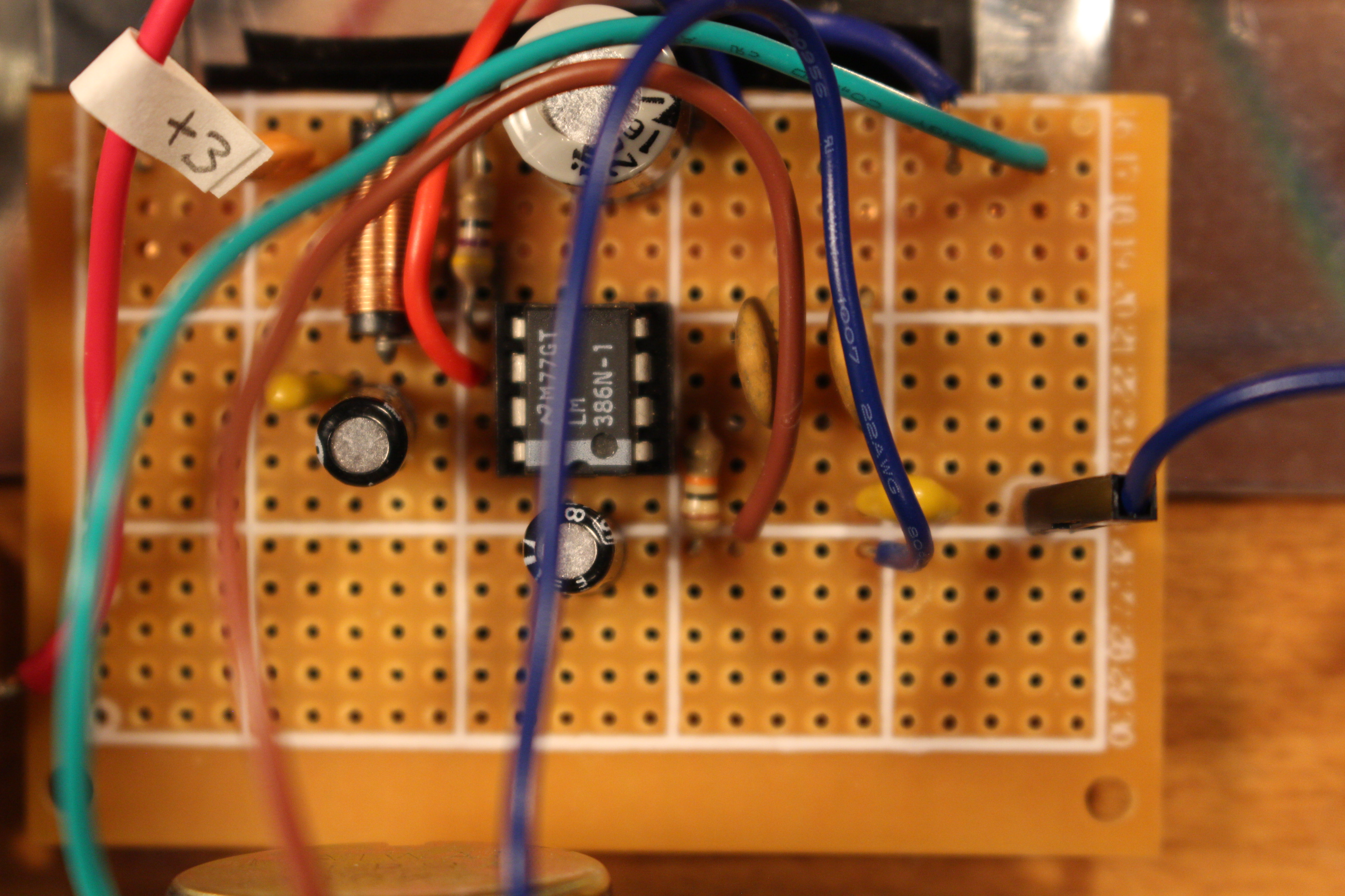 Audio amplifier board (top)
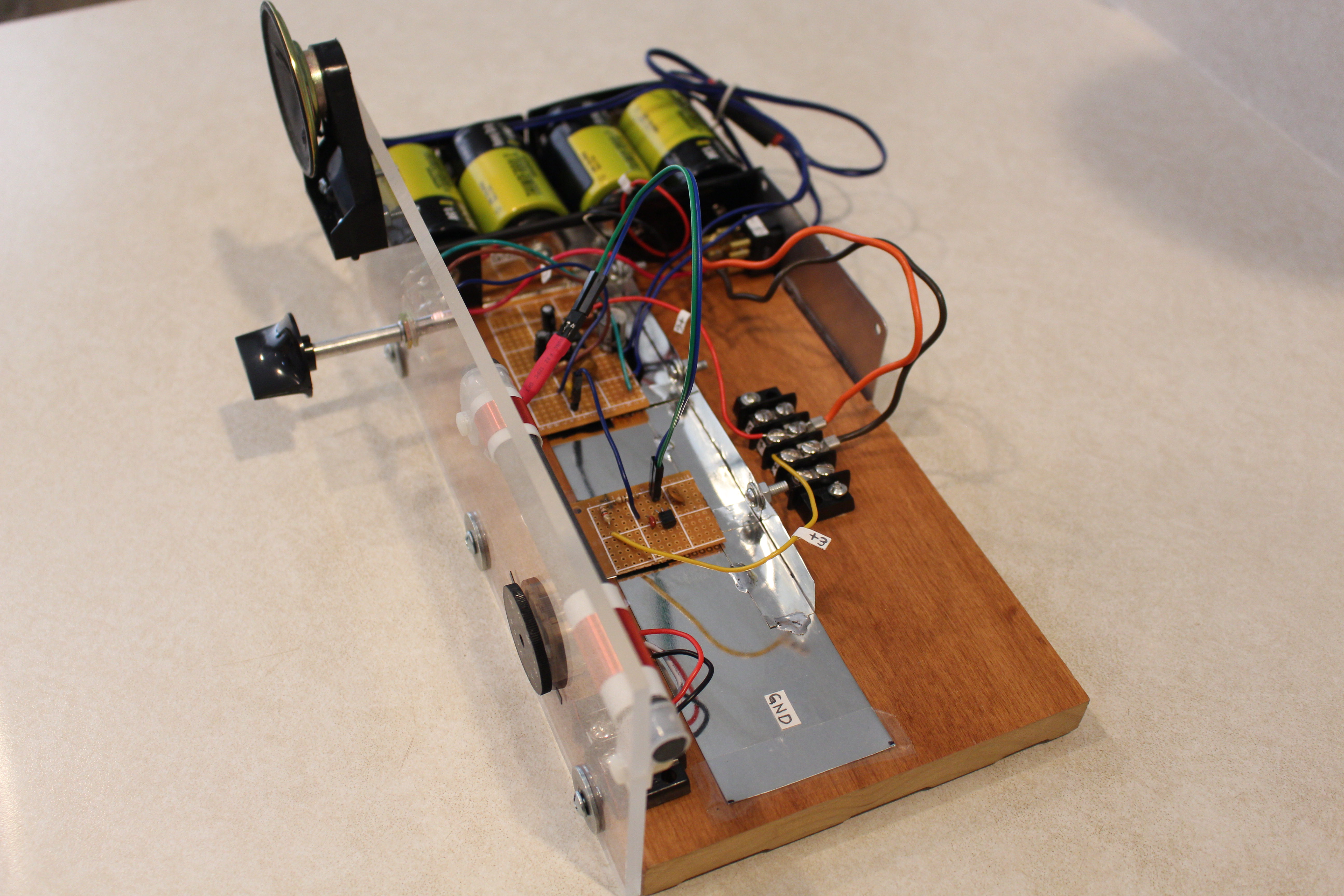
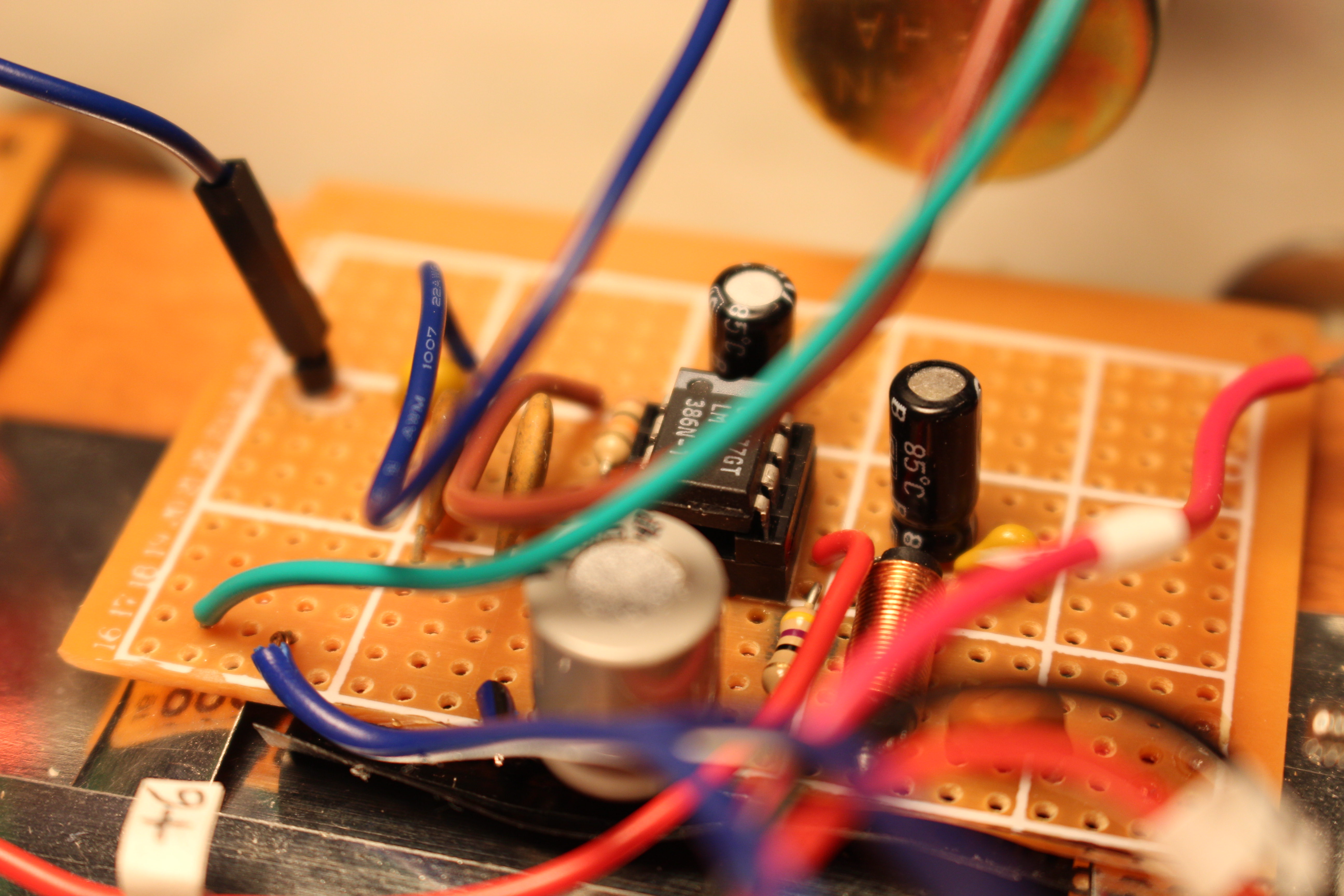 Audio amplifier board (side)

The AM detector and the audio amplifier circuits are implemented each on a separate perfboard and sit on a tin strip ground plane. A tin strip is soldered to the ground wires on the bottom of each board, and electrical tape covers the relevant parts of the bottom of each board to prevent shorting to ground. The tin strip attached to each board is securely connected to the main ground plane via a small metal machine screw and nut by bending each board's tin strip up by 90 degrees, likewise the edge of the ground plane, then drilling or punching a hole through each to insert the machine screw.
The ferrite rod is Mn-Zn, size 140 mm by 10 mm and appears to be type 63. It is mounted to the acrylic panel with plastic cable clamps.
The two coils that slide over the ferrite rod are made of 30 AWG magnet wire wound on round polystyrene tube from Evergreen Scale Models part #234. The wire is affixed to the polystyrene tube via superglue and a hole, slightly bigger than the wire, at each end of the tube through which the wire is drawn. The hole is made by hand with a pin vise hand drill. The diameter of the 30 AWG magnet wire is 0.0109 inch (0.277 mm).
The variable mechanical capacitor has 3 contacts whose combinations produce various capacitance ranges. Testing all combinations, we ended up tying the 2 outer contacts together, giving a capacitance versus the inner contact of 35-240 pF.
The ground plane and tin strips soldered to the bottom of each circuit board are cut from tin coated sheet metal that is 0.008 inch (0.2 mm) thick. It comes in 4 x 10 inch (10.2 x 25.4 cm) sheets from K&S Metals part #254.
The clear acrylic front panel has dimensions 101/4 x 4 x 3/16 inch (26 x 10 x 0.476 cm). The hole positions are shown below.

The power switch on the back of the radio is type DPST so that both 3 and 6 volt power are simultaneously turned on/off. The power switch was mounted on a piece of scrap aluminum plate of size 33/4 x 2 x 5/128 inch (95 x 51 x 1 mm). The hole for the switch was cut out with a metal hand nibbler and finished with a file.
The perf board dimensions of the AM detector board is 1 5/8 x 1 3/16 inch (41 x 30 mm), and that of the audio amplifier board is 2 5/8 x 1 3/4 inch (67 x 44 mm).
Parts list for AM detector board:
- TA7642 AM radio IC
- variable mechanical capacitor
- ferrite loop stick antenna
- 0.01uF ceramic capacitor
- 100K carbon resistor
- 1K carbon resistor
- 0.1uF ceramic capacitor
Parts list for audio amplifier board:
- 10uF ceramic capacitor
- 10K audio taper potentiometer
- 10K carbon resistor
- 2nF ceramic capacitor
- 0.1uF ceramic capacitor
- 10uF electrolytic capacitors, Qty 2
- RF choke
- 47 ohm carbon resistor
- 47nF ceramic capacitor
- 220uF electrolytic capacitor
- 8 ohm speaker, 0.5 W, 2.25 inch (57 mm) diameter
- LM386 DIP
- DIP socket
Last modified: 2024-07-20
Copyright 2024 by Exstrom Laboratories LLC