Introduction
An encounter with the mysterious, that some people never forget, is when they are first given magnets to play with as children. What is this strange force that pulls the magnets together? There is seemingly nothing but empty space between the magnets and yet there is something that either tries to pull them together or push them apart, depending on how they are oriented. This fascinating little phenomena can keep a child busy playing and experimenting for hours. Some children never loose their fascination and go on to become engineers and physicists. That magnetism is indeed a very deep phenomena becomes apparent the more you study physics. To fit magnetism into its proper place in nature requires building up a significant framework of physical theories that includes relativity and quantum theory. But it is not necessary to understand magnetism on such a level in order to get a good intuitive feel for the phenomena and to put it to good use. This book is about using one of natures smallest magnets, the proton, to measure the strength of magnetic fields. The device used to do this is called a proton precession magnetometer and the fact that such a device works at all is, in our opinion, one of the wonders of nature. Maybe, we hope, it will inspire you to learn more about the phenomena of magnetism.
1.1 The proton precession magnetometer
A proton precession magnetometer ( PPM ) is one of the most accurate devices that you can build for measuring magnetic fields. A PPM takes advantage of the fact that protons have an intrinsic magnetic field, much like an exceedingly small magnet. When the protons are placed in an external magnetic field, the direction of their field will precess (rotate) about the direction of the external field. The frequency of precession is directly proportional to the strength of the external field. The proportionality constant, called the gyromagnetic ratio of the proton, is known to a very high degree of accuracy. When enough protons are precessing in sync about an external field, they will produce an oscillating magnetic field, due to the combined effect of each of their precessing fields. The frequency of this oscillating field is ultimately what is measured by the PPM and since it is equal to the precession frequency of the protons it can be used to determine the strength of the external field. This short definitional description of a PPM should become somewhat clearer as the instrument is described in more detail below.
Our goal is to describe, in detail, the construction and operation of a PPM called the Magnum. The Magnum is designed for operation in the Earth’s magnetic field or in any magnetic field that is less than about 100,000 nano-Tesla and is uniform over a minimum volume of 1 cubic foot. There are many potential applications for a device like the Magnum. The obvious application is to simply use it to make precision measurements of the Earth’s magnetic field. By making periodic measurements, you can create a record of the daily and seasonal variations of the field and monitor magnetic storms. There are a network of magnetic obervatories around the world that continuously monitor the Earth’s magnetic field and you can compare your measurements with the that of the closest observatory. The U.S. Geological Survey runs the National Geomagnetism Program which has links to all the magnetic observatories in the United States. There is also an international magnetic observatory network called Intermagnet that has links to magnetic observatories spread throughout the world. If there is no observatory near you then you can contribute your observations to the scientific study of the Earth’s magnetic field.
The Magnum can be used to detect magnetic anomalies due to ferromagnetic objects in the environment. The presence of a nearby automobile, building, or any structure with a significant amount of steel, will have an effect on the Earth’s field that can be measured with the Magnum. Buried and underwater ferromagnetic objects can also be detected but the spatial resolution will be low. It is possible to modify a Magnum or use more than one of them to improve the spatial resolution but we will leave it to the reader to figure out how to do this.
Calibrating low field magnetometers is another possible application. Magnetometers that use Hall Effect or GMR sensors must be calibrated for them to be effective. The Magnum does not need to be calibrated (the calibration is built into the physical properties of the proton ) and so can provide a highly accurate field measurement against which these other magnetometers can be compared. You can for instance callibrate a GMR sensor based magnetometer and then use it for mapping the Earth’s field over a large area. This is difficult to do with the Magnum because of its size and weight.
With the Magnum you can measure the nuclear magnetic relaxation time of various proton rich liquids. It thus provides a great introduction to the idea of manipulating the magnetic moments of atomic nuclei. This is the same basic idea that is used in nuclear magnetic resonance ( NMR ) and magnetic resonance imaging ( MRI ), except that in these cases the magnetic moments are manipulated in a somewhat more sophisticated manner which we will not discuss here.
The Magnum is also an excellent introduction to scientific instrument design. Basic instrumentation components such as, sensors, signal conditioning, low noise amplification, data acquisition, data analysis, and precision control are all part of the Magnum. In the following chapters the design and construction of the Magnum will be described in detail. In the rest of this chapter we will describe the basic physics behind the operation of the instrument and give a general description of its overall design.
1.2 How PPM’s work
To get a feel for what is happening in a proton precession magnetometer lets start by looking at a magnetic compass of the kind that was used for navigation before the GPS came along. If you set the compass on a flat surface, the needle will eventually come to rest, aligned with the Earth’s magnetic field. As you probably know, the reason for this is that the compass needle is itself a small magnet and magnets align with the magnetic field that they find themselves in. In this case the north pole of the compass needle is attracted to the magnetic south pole of the Earth 1.
|
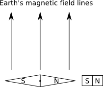
| Figure 1: Compass near strong magnet |
If you now take another magnet, whose field is much stronger than the Earth’s, and place it next to the compass, so that its magnetic axis (north-south pole line) is perpendicular to the magnetic axis of the Earth, then the compass needle will realign itself in the direction of the stronger magnet (see figure 1). When the stronger magnet is suddenly removed, the compass needle will once again try to align itself with the Earth’s field and it will begin to swing back in that direction. When it swings back and reaches alignment it will however not stay there. The needle has acquired some angular momentum during its swing and so it will overshoot the alignment and become misaligned in the opposite direction. The attraction of the Earth’s field will however put the brakes on, and make the needle reverse direction back toward alignment.
|
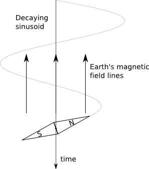
| Figure 2: Compass needle settling down to alignment with Earth’s field. |
To cut a long story short, the needle will oscillate back and forth around the direction of the Earth’s field, and eventually settle down in alignment with it. An actual compass needle is usually immersed in a fluid that acts to dampen the oscillations so that it will settle down very quickly into alignment with the Earth’s field. If the needle were allowed to freely rotate then the oscillations would continue for much longer before settling down. Now if you were to plot the position of the tip of the needle as a function of time you would get a decaying sinusoid as shown in figure 2. The interesting thing about this is that it is precisely the same waveform that is produced by a PPM and this more than just a coincidence.
Like a compass needle, the protons that produce the signal in a PPM have an intrinsic magnetic field and for our purposes we can think of them as a bunch of tiny compass needles or magnets. There are however some crucial differences between a proton and a compass needle. To begin with, a proton is not constrained to rotate about a fixed axis like a compass needle. The proton, and hence the direction of its magnetic field, is generally free to rotate in three dimensional space. Another difference is that the proton has an intrinsic angular momentum, in addition to its intrinsic magnetic field. This means that the proton behaves like a small gyroscope or spinning top that also happens to be a magnet.
If you’ve ever played with a spinning top, you will recall that when the axis of rotation of the top becomes tilted with respect to the vertical (direction of the gravitational force) then the top will start to rotate or precess about the vertical axis. Essentially the same thing happens with a proton when it is placed in a magnetic field. In this case the magnetic field exerts a force on the proton, in the same way that the Earth’s field exerts a force on a compass needle, to try to align it with the field. However since the proton is also a spinning top, instead of its field aligning with the external field, it will precess about the direction of the external field just like the spinning top will precess about the direction of the gravitational field.
In a large collection of protons not all of them will be precessing about the magnetic field. The protons interact with each other and with other charged particles such as electrons. The electrons also have intrinsic magnetic fields that can perturb the protons and prevent them from aligning with the field. There will however be a significant number of protons that are precessing about the field and the components of their magnetic fields, that lie in the direction of the external field, will add up to produce some net field. This net field is the origin of what is called nuclear paramagnetism and its strength is proportional to the strength of the external field. 2
Now look at what happens if we have a bunch of protons in a very strong magnetic field at right angles to a weak field. The strong field will produce some net alignment of the protons in its direction. We say then that the protons have been polarized by the strong field. If the strong field is suddenly set to zero then the only thing that remains is the weak field and the protons will all begin to precess about it in synchronization. This has the effect of rotating the net polarization field produced by the strong field about the direction of the weak field. Recall that this is similar to what happened when the strong magnet was suddenly moved away from the compass needle and the needle then began to rotate back and forth about the weaker Earth field. If an inductive coil is placed around the protons then the rotating polarization field will induce a voltage in the coil which, although extremely weak, can be amplified and measured.
The rotating polarization field will however decay at an exponential rate. This is because the protons become desynchronized so that their fields begin to cancel each other out. The exponential time constant for the decay is called the relaxation time constant and is usually denoted as T2. The exact value of T2 will depend on the substance in which the protons are embeded. For the Magnum this will usually be some type of proton rich liquid such as water or alcohol. For such liquids T2 will be on the order of a few seconds and the usable signal will usually be no more than 2 or 3 seconds.
In the above discussion about protons we never specified exactly which protons we were talking about. As you may know, the nuclei of all atoms contain protons and neutrons, both of which have magnetic fields. These magnetic fields are strongly coupled with each other and they combine to produce a net magnetic field for the nucleus. For the purposes of a device such as the Magnum or for any NMR instrument, it is only the net magnetic field of the nucleus that can be can be manipulated by external magnetic fields. The individual protons in a nucleus heavier than hydrogen 3 can not be manipulated in a way that is useful for a PPM.
It is possible in principle to use nuclei heavier than hydrogen in a magnetometer like the Magnum but the signal they produce is too weak to be used in practice. The Magnum is designed to use only the single isolated proton found in the most common isotope of hydrogen. Single protons have the largest magnetic fields and therefore produce the strongest signals. The signal produced by single protons also has the highest frequency and is therefore the easiest to detect with the inductive sensor used by the Magnum. Another good reason to use single protons is that there are so many compounds that contain hydrogen atoms. Water is the most common but organic compounds such as alcohol and paraffin can also be used. Paraffin is particularly dense in hydrogen and was actually the substance used by Purcell, Pound, and Torrey in their discovery of nuclear magnetic resonance, for which they won the Nobel Prize.
The above discussion should give you a general idea of what a PPM is and the basic principles behind how it operates. If you are interested in learning more about magnetism and nuclear magnetic resonance see the Bibliography at the end of this book. What follows is a brief overview of the operation and design of the Magnum. The individual components of the instrument will be described in detail in the following chapters.
1.3 Overview of magnetometer
First a general description of how to operate the Magnum. You begin by selecting some hydrogen rich substance such as water, alcohol, or paraffin, which we will refer to from here on as the sample. You place about two ounces (59 ml) of the sample inside a cylindrical plastic bottle. The bottle is placed inside the sample coil which is then placed inside the polarization coil. The sample is polarized for a period of time with the field generated by the polarization coil. When the polarization coil is switched off, the signal generated by the precessing protons in the sample is recorded by the data acquisition system. The digitized signal is then processed using software to produce a spectrum which gives the precession frequency of the protons.
|
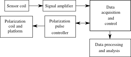
| Figure 3: Magnum system diagram. |
Now we give a description of the overall design of the instrument. A general system diagram is shown in figure 3. The Magnum can roughly be divided into three parts: the polarization system, the sensor system, and the control and data acquisition system. We start with the polarization system.
The purpose of the polarization system is to generate a large magnetic field (relative to the Earth) that is in a direction perpendicular to the Earth’s field. The polarization field is generated by a large coil which is mounted on a tiltable platform. The tiltable platform is needed to allow the direction of the polarization field to be aligned perpendicular to the Earth’s field. The polarization field must be capable of being turned on for a specific period of time and then turned off very quickly. The polarization pulse controller is designed for this purpose. The controller can be programmed by the operator via a serial link to a personal computer. Once programmed, the controller waits for a signal from the PC to start the polarization process. This process consists of turning on the current to the polarization coil for the specified period of time, turning off the current quickly, and then signaling the data acquisition system to begin taking data. The polarization coil, tiltable platform, and pulse controller will be described in detail in subsequent chapters.
The sensor system consists of two parts, the sample coil and the amplifier. The sample coil holds the bottle containing the sample. Its purpose is to inductively pick up the very small oscillating magnetic field produced by the polarized protons precessing about the Earth’s magnetic field. The sample coil actually consists of two identical coils placed side by side. One coil is used to house the sample and the other is used to cancel out environmental magnetic fields. Either one of the coils can be used to house the sample but you cannot put a sample in both coils since the two signals would cancel out. The signal produced by the precessing protons is extremely weak. To boost the signal, the sample coil must be tuned using capacitors to form a resonant circuit at the proton precession frequency. The amplifier has a bank of capacitors that can be used to tune the sample coil. The amplifier will also amplify the signal from the tuned sample coil by a factor of about 3.8 million. An amplifier with such a high gain is a very sensitive device and it must be constructed very carefully to prevent it from turning into an oscillator. Details of the construction of the amplifier and the sample coil can be found in the following chapters.
The data acquisition and control system consists of a personal computer with a pci data acquisition card and some software. The software allows the operator to program the pulse controller and then start the polarization and data acquisition process. Multiple cycles of polarization and data acquisition can be controlled by the software. The data from each cycle is averaged together to get a higher signal to noise ratio. The software can program the pulse controller to turn on the polarization field for anywhere from a fraction of a second to several seconds. After it sends a signal to the pulse controller to start the polarization, it initializes the data acquisition system to wait for a signal back from the controller indicating that the polarization has finished and data acquisition can start. Channel selection, setup and sampling rate of the data acquisition system is also controlled by the software. After all the data has been collected, additional software is used to filter the data and calculate the spectrum of the signal. The spectrum then gives the proton precession frequency from which the magnetic field can be calculated. All of this will be described in more detail in the following chapters.
1 The north pole of a magnet is defined as the pole that points toward the geographic north pole of the Earth when the magnet is free to rotate. Since opposite poles attract this means that the magnetic south pole of the Earth is actually near the geographic north pole. We have to say near because the magnetic and geographic poles do not coincide. We should perhaps also define what we mean by magnetic and geographic poles. The magnetic poles are where the magnetic field lines are oriented vertically. At the north magnetic pole the field lines point vertically out of the Earth and at the south magnetic pole the lines point vertically into the Earth. The geographic poles are where the axis of rotation of the Earth intersects the surface of the Earth. The south magnetic pole is close to the north geographic pole and vice versa.
2 This is true to a first approximation. There is something similar to feedback that can occur in paramagnetism that will introduce some nonlinearities but it is very weak and can usually be ignored. If these nonlinearities where too large then we would get spontaneous magnetization and the system would be called ferromagnetic and not paramagnetic.
3 Hydrogen has the lightest nucleus of all the elements. There are three forms, or isotopes, of Hydrogen. The most abundant isotope has only a single proton in the nucleus. The other two isotopes have one or two neutrons in addition to the proton and are relatively rare. When we talk about Hydrogen from here on, it will be assumed that we mean the single proton form.