Polarization Coil and Platform
2.1 Materials not allowed
The polarization coil and tiltable platform upon which it sits must not contain any ferromagnetic material, since this would alter the natural uniformity of the Earth’s field, resulting in varying precession frequencies of the protons within the sample, and weakening the signal induced in the sample coil. For the same reason, care must be taken that there are no ferromagnetic materials under or near the polarization coil and platform, and the polarization coil/sensor coil should be placed outside of buildings, when in operation, since most buildings contain large amounts of ferromagnetic materials in their infrastructure (steel I-beams, airducts, nails, etc).
One of our customers once asked whether placing the entire coil assembly inside of a large nonferromagnetic metal box would eliminate magnetic field noise. This is definitely NOT a good idea. Doing so would induce eddy currents in the box when the polarization coil current is turned off, corrupting the magnetic field in the region of the sample, and dashing all hope of getting a signal in the sample coil. For this reason, you want to keep away from the polarization coil any large metallic objects, whether ferromagnetic or not.
2.2 Wire for polarizing coil
A current of approximately 10 amps is sent through the polarizing coil to polarize the sample. The wire size used for the polarizing coil must be large enough to handle this current. We use a 14 gauge, 600 volt THHN insulated solid copper wire for the polarizing coil, and a 16 gauge, 300 volt flexible stranded lamp cord for the 50 ft (15 meters) long connection from the polarizing coil to the pulse controller. The slightly thinner lamp cord is OK since it is not wound like the coil wire and doesn’t have much more resistance, but if you can find a 14 gauge lamp cord, you can use that. Note that this would slightly increase the current through the polarizing coil.
The pulse controller turns off the approximately 10 amps of current going through the polarizing coil in about 300 milliseconds. This quick turnoff induces a large voltage of about 270 volts. Therefore the voltage rating of the wire used in constructing the polarizing coil is important. Note that we use a 600 volt wire for the polarizing coil itself, and a 300 volt wire for connection to the coil. Of course you can use a higher voltage wire than this. Keep in mind that the voltage rating of a wire is solely dependent on the wire’s insulation, not the wire itself.
2.3 Purpose of polarizing coil
The purpose of the polarizing coil is to produce a magnetic field much greater than that of the Earth’s, so that the majority of the population of protons in the sample are precessing about the field of the coil and not the Earth’s field. For this reason, the field produced by the polarizing coil need not be especially uniform, as long as it is large compared to the Earth’s field. In fact this property inspired the name Magnum since it is a brute force method of manipulating the spins of nuclei.
2.4 Positioning polarizing coil
The symmetry axis (the axis around which the coil is wound) of the polarization coil should be oriented so that it is perpendicular to the Earth’s magnetic field. In the northern hemisphere, the magnetic field enters the ground at an angle called the magnetic inclination. The polarization coil must therefore be tilted from the horizontal by an amount equal to the magnetic inclination angle. So to properly align the coil, orient the platform on which the coil is mounted (using a standard magnetic compass ), such that the axis about which the coil tilts, is perpendicular to the magnetic north direction, and tilt the coil by an amount equal to the magnetic inclination. The coil is held in the tilted position by two brass strips that slide onto rods on either side of the platform. The holes in the brass strips allow the angle to be fixed at approximately five degree increments from zero to ninety degrees.
The following websites provide geomagnetic data to allow magnetic inclination angle to be calculated at most locations on the Earth:
USGS Observatories,
http://geomag.usgs.gov/observatories/INTERMAGNET Participating Observatories,
http://www.intermagnet.org/Imomap_e.htmlDGRF/IGRF Geomagnetic Field Model,
http://modelweb.gsfc.nasa.gov/models/igrf.html
As an example, the magnetic inclination angle in Longmont, Colorado is approximately 65 degrees. The polarization coil must therefore be aligned as shown in figure 4.
 |
| Figure 4: Magnetic inclination angle and coil alignment in Longmont, Colorado. |
2.5 Inductance of a coil
Knowing the approximate inductance of a coil is necessary, for example, to calculate the voltage induced when the current is turned off, and later, for calculating the resonant frequency of a sample coil, given a capacitance. The inductance of a coil can be approximated with the following formula [20, p42-44].
where

and r = mean radius [cm], t = thickness of windings [cm], l = length of coil [cm], N = total number of turns.
2.6 Magnetic field strength due to coil
It is important to know approximately the strength of the magnetic field inside the polarization coil, so that one knows that the field is sufficiently large to get a proton precession signal. The magnetic field, in units of Tesla, due to a multilayered finite length solenoid is
![B(x)=(\frac{\mu n^{2}I}{2})\left[(\frac{h}{2}-x)\ln(a(x))+(\frac{h}{2}+x)\ln(b(x))\right]](ch2-Z-G-4.gif)
where x is the distance from the geometric center of the coil along
its axis, μ = 4π*10-7 Tesla*meters/Amperes, n is turns/meter
of the wire, I is the current through the solenoid in Amperes,
h is the length of the coil in meters,  is the natural logarithm
(
is the natural logarithm
( base e ), and
where r1 and r2 are the inner radius and outer radius, respectively, of the coil in meters.
What is the minimum field strength needed from the polarizing coil in order to get a good signal out of the sample coil? The short answer is, the larger the better, since a stronger field produces a stronger signal, but of course there are practical limits. For the specifications given in this book, you should have about 75 Gauss in the geometric center of the polarizing coil, i.e. B(0)≈0.0075 in the formula above.
2.7 Polarizing coil parts list
Acrylic tube, 4.5 inch (11.43 cm) outer diameter, 4 inch (10.16 cm) long, 1/8 inch (0.3175 cm) thick.
2 Acrylic squares (end pieces), 6 inch (15.24 cm) on a side, 5/32 inch (0.397 cm) thick.
14 AWG solid copper wire, 289 feet (88.1 meter).
14 AWG copper speaker wire, 50 feet (15.2 meter).
Spade Terminals for 14 AWG wire, Qty 2, Mouser Part#538-19144-0015.
 |
| Figure 5: Wound polarizing coil form. |
2.8 Specifications of polarizing coil
14 AWG solid copper wire, wire diameter(w/o insul) = 1.63 mm
coil inner diameter = 11.4 cm
coil length = 10.0 cm
number of wire layers = 6
turns/layer = 38 => total number of turns = 228
thickness of windings = 1.43 cm
Approximate inductance = 4.3 mH
Approximate resistance = 1.1 Ohm
Approximate self capacitance = 570 pF
2.9 Construction of polarizing coil
The polarizing coil form is composed of three parts, all made of acrylic (also called plexiglass ): the tube, and the two end pieces. The two end pieces, which are squares 6 inches (15.24 cm) on a side, need to have circular holes with a diameter of 4 1/4 inches (10.795 cm) drilled into their centers. Keep one of the discs left over from drilling the holes. It will be used later for attaching to the sample coil. Four small holes need to be drilled near each of the corners of one end piece so that the polarizing coil can be attached to the tiltable platform. Acrylic solvent can then be used to glue the end pieces onto the tube. The acrylic and solvent can be purchased at a plastics supplies store.
2.10 Tiltable platform parts list
Top, white acrylic, 0.5 x 6 x 6 inches (1.27 x 15.24 x 15.24 cm).
Bottom, white acrylic, 0.5 x 6 x 15 inches (1.27 x 15.24 x 38.1 cm).
2 Acrylic hinges.
Brass strips, 1/4 x 1/16 x 12 inches (0.635 x 0.159 x 30.5 cm).
Brass rod, diameter 3/32 inches (0.238 cm).
4 Nylon machine screws, 8-32 x 1 inch (2.54 cm).
4 Nylon nuts.
4 Nylon washers.
2 rubber bumpers (attach to the bottom of the top piece of acrylic to separate the two pieces).
 |
| Figure 6: Tiltable platform with polarizing coil mounted on it. |
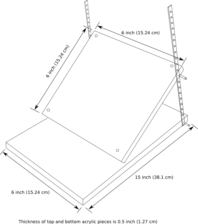 |
| Figure 7: Tiltable platform drawing. |
2.11 Construction of tiltable platform
The top piece of the tiltable platform needs to have four holes drilled into each of its four corners, so that the polarizing coil can be mounted on it, using the nylon machine screws.
Two acrylic hinges are used to physically attach the top and bottom pieces together. The arylic hinges are glued to the two pieces using acrylic solvent.
Holes are drilled into the sides of the platform, opposite the hinges, so that brass rods, can be inserted. The holes should be just wide enough for the rods to snuggly slide in, and should be about 1/2 inch (1.27 cm) deep. Cut 4 rods about 1 inch (2.54 cm) long, and slide them into the holes with a dab of glue so that they won’t ever come out, and so that they protrude out about 1/2 inch. These brass rods are for attaching the brass strips, so that the platform angle can be adjusted. The two brass strips need to have holes drilled into them so that the platform angle can be adjusted in 5 degree increments.