Pulse Controller
3.1 Purpose of pulse controller
The pulse controller is used to turn the current in the polarization coil on and off. The time it takes to turn on the current is not critical but the time it takes to turn it off is. To get a good precession signal, the polarization field has to be turned off as fast as possible. If the polarization field decays slowly then the proton magnetic moments will simply follow the field and you will end up with no precession signal.
Quickly turning off a large amount of current in a large coil is a tricky business. There is a significant amount of energy stored in the magnetic field of the coil and this energy has to go somewhere. The problem is entirely analogous to trying to stop a large truck moving at high speed in as short a distance as possible without damaging it.
3.2 Quenching the current
You can probably think of many ways of trying to tackle this problem. The simplest solution that immediately comes to mind is to use a mechanical relay. There are several problems with this. First of all, a mechanical device like a relay has a relatively short lifetime compared to solid state switching devices like transistors. In a PPM like the Magnum, the current will be switched on and off so many times that a mechanical relay will fail rather quickly.
Another problem with relays is that they do not turn on and off cleanly and predictably. A relay is basically just a switch like the light switch is your house and the contacts, like any switch will tend to stick when you open them and bounce when you close them. A final problem is the possibility of electric arcing across the contacts when you open them due to the large voltage induced in the coil when the current is turned off.
The problem of quickly turning off the current in a coil has been around for a long time and there was really no good reliable solution until the invention of semiconductor power devices. Some of the early circuits using these devices where composed of a complex and sometimes ingenious combination of zener diodes, resistors, large capacitors, and silicon controlled rectifiers (SCR’s ). Semiconductor power devices have evolved a great deal since then and a much simpler solution is now possible using a device called a power MOSFET.
3.3 How a MOSFET works
The type of MOSFET used in the magnum is called a p-channel enhancement type. It is basically a solid state switch. The device has three terminals called the source, drain and gate. The gate voltage controls the current flow through the device from the source to the drain 1. In a p-channel MOSFET the gate to source voltage must be negative to allow source to drain current to flow. The lower the gate voltage is with respect to the source voltage, the more current will flow through the device, up to a certain point.
Like all real devices, a MOSFET has limits. The MOSFETs used in the pulse controller are IRF6215’s made by International Rectifier. They have a maximum allowable gate to source voltage of -20 volts. The amount of current that can flow through the device and the amount of power it can dissipate is also limited. Another important factor to take into account is the drain to source breakdown voltage. This is the voltage at which current will be conducted through the device even though it is in the off state. This is similar to what happens in a mechanical switch, when the voltage between the contacts gets too high you will get an electrical arc and current flow even though the switch is open.
3.4 Advantage of using multiple MOSFETs
Fortunately, some of the limitations of a single MOSFET can be overcome by using several of them together. You can increase the effective drain to source breakdown voltage by putting two of them in series. This will double the break down voltage. A problem with this however, is that a MOSFET with current flowing through it will always have a voltage drop across it and therefore some finite resistance. This resistance is called the on-resistance and if you put two MOSFETs in series you effectively double the on-resistance.
From elementary circuit theory you know that putting two resistors of equal value in parallel will give you an equivalent resistance of half the value. The solution to the problem of the doubling of the on-resistance is then to use a parallel combination of two MOSFETs in series for a total of four MOSFETs. This will give you a doubling of the breakdown voltage without increasing the on-resistance.
3.5 Pulse controller circuit description
The schematic for the Magnum pulse controller circuit is shown in figure 8. Note that two parallel combinations of four MOSFETs are placed in series. A parallel combinaton of four MOSFETs gives an effective on-resistance of one fourth the on-resistance of a single MOSFET. Putting two of these combinations in series will then result in an overall effective resistance of one half the on-resistance of a single MOSFET. The two combinations in series will also double the effective breakdown voltage. The IRF6215 has an on-resistance of about 0.3 ohms 2 and a minimum breakdown voltage of about 150 volts. With the eight IRF6215s arranged as in the Magnum circuit the effective on-resistance is then 0.15 ohms and the breakdown voltage is 300 volts.
A positive twelve volt power supply is connected directly to the source terminals of the first parallel combination of IRF6215’s and the polarization coil is connected directly to the drain terminals of the second parallel combination of IRF6215’s. When the IRF6215’s are turned on we then effectively have a 12 volt supply in series with the 0.15 ohm resistance of the IRF6215s, and the 1.1 ohm resistance and 4.3 mH inductance of the polarization coil. This will deliver approximately 12/1.25 = 9.6 amps of current 3 to the polarization coil.
The level of the gate voltage on all eight of the IRF6215’s is controlled by an Atmel AT90S2313 8-bit microcontroller. To avoid potential damage to the AT90S2313, due to the large induced voltages during switching, the gate voltage is actually controlled through a 4N35 optocoupler. When the output of pin PB0 on the AT90S2313 is high the transistor on the output side of the 4N35 is turned off. This puts the gate voltage of the IRF6215’s at approximately 12 volts so that the gate to source voltage is about zero and the devices are turned off. When pin PB0 goes low the output transitor of the 4N35 is turned on, which causes the gate voltage of the IRF6215’s to drop to about 1 volt. The gate to source voltage is then approximately -11 volts and the IRF6215’s are turned on, allowing the polarization current to flow through the coil.
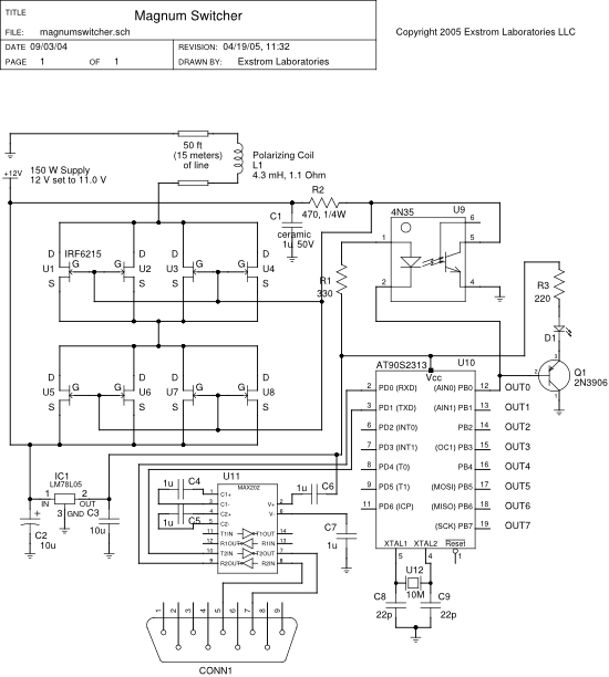 |
| Figure 8: Magnum pulse controller and microcontroller circuits. |
3.6 Microcontroller circuit description
The voltage supply for the AT90S2313 microcontroller is provided by an LM78L05 voltage regulator that takes the same 12 volt supply used to power the polarization coil, and reduces it to the 5 volts needed by the AT90S2313. The clock speed of the AT90S2313 is set to 10 MHz by the crystal and capacitors connected to pins XTAL1 and XTAL2. Pin PB0 of the AT90S2313, which controls the gate voltage of the MOSFETs is also connected to a 2N3906 transistor that drives an indicator LED which turns on when current is being applied to the polarization coil. All 8 pins of port B on the AT90S2313 are connected to a terminal block on the front of the pulse controller housing. Each of these pins can be individually programmed to turn off and on for specified periods of time as described in the section below on the microcontroller software.
Pins PD0 and PD1 of the AT90S2313 are connected to a MAX202 which is an RS232 driver IC. This IC provides an interface to an RS232 serial port. The serial port is used to allow a PC to communicate with the AT90S2313. The PC can send a pulse program to the AT90S2313 which tells it how long to turn on the polarization current, and then how long to wait before signaling the data acquisition system to start taking data, after the polarization current has been turned off. After the AT90S2313 has been programmed it waits for a signal from the PC to run its program.
3.7 Microcontroller software
The microcontroller software is written in the assembly language of the AT90S2313. The software listing is given in Appendix B. What follows is a general description of how the microcontroller is programmed to behave.
The AT90S2313 continuously listens on the RS232 port for commands from the PC. Its software is completely interrupt driven so that it can respond to commands even during the execution of the pulse program. The five commands that it recognizes are
Set Program: the PC transmits this command when it wants to send a new pulse program. After receiving this command the AT90S2313 waits to recieve a new program from the PC which it then stores in memory for later execution.
Get Program: the PC transmits this command when it wants the AT90S2313 to send it the pulse program that it has stored in memory. This is useful for verifying that the stored program is correct and has not been corrupted somehow durring transmission to the AT90S2313.
Run Program: the PC transmits this command when it wants the AT90S2313 to start executing the pulse program that it has stored in memory. The AT90S2313 will execute the program and then once again go into an idle state where it listens for the next command.
Loop Program: this is like the Run Program command except that it tells the AT90S2313 to run the pulse program in a continuous loop. After executing the program once it immediately begins executing it again and it continues doing this until it receives another command.
Stop Program: this command tells the AT90S2313 to immediately stop what it is doing and go into an idle state where it just listens for another command from the PC.
The program for the AT90S2313 can be represented as a series of states that the device cycles through. A state is specified by the value of the 8 pins on port B of the device. The value of these 8 pins can be represented by a 8 bit binary number. A low value on one of the pins is taken to be a logic 1, or the on-state, and a high value is taken to be a logic 0, or the off-state. If for example pins PB0 and PB2 are low and all the other pins are high, this can be represented by the binary number 00000101 = 5. To specify a state with all pins set low (logic 1, on-state), use the value 255 = 11111111.
The length of time that a state remains active is specified by two additional bytes. If t is the length of time in units of micro-seconds (1000000 micro-seconds = 1 second), that the state should remain active, then the value of these two bytes is given by the formula:
65536 - int( 5 * t / 512 )
where int() means take the integer part of the argument. The value of t can range from 102.4 to 6710886 micro-seconds which is 0.0001024 to 6.710886 seconds.
A state is then completely specified by 3 bytes. The first byte gives the value of the output pins and the next two bytes give the time that the state remains active or on. A program can have a maximum of 10 states. The AT90S2313 remains in a state for the specified period of time and then transitions to the next state. If the device is in loop mode when the time runs out on the last state, it will loop back to the fist state and continue, otherwise it will remain in the last state. It is important to keep in mind that the device remains in the last state when the program finishes unless it is in loop mode.
The process of actually programing the AT90S2313 is handled by software running on a PC. The software allows the states and times to be specified very easily in a parameter file and it calculates the necessary byte values so that you don’t actually need to use the above equation. This software will be discussed in a following chapter.
3.8 Power supply
The power supply used for supplying current to the polarizing coil and to the microcontroller circuit (through an LM78L05) is a 12 volt, 150 watt, Meanwell power supply (Manufacturer#S-150-12). Other power supplies might be usable, but the two important properties that must be considered are the power, and the ability to withstand transients at the output. Another good thing about the Meanwell power supply is that it fits inside the enclosure specified in the parts list.
3.9 Assembly and enclosure
Figure 9 shows the physical layout of the MOSFETs. All 8 MOSFETs are mounted on a single aluminum bar (5.6 inch (142mm) long x 1.0 inch (25.4 mm) wide x 1/8 inch (3.175 mm) thick), with thermal pads (see parts list) between the MOSFETs and the bar. The aluminum bar is, in turn, attached to the enclosure of the pulse controller. This provides a good heatsink, and ties all the MOSFETs together thermally. The fact that the MOSFETs have a common thermal connection is important because the speed at which MOSFETs switch is temperature dependent. Their switching speed slows as they get hotter.
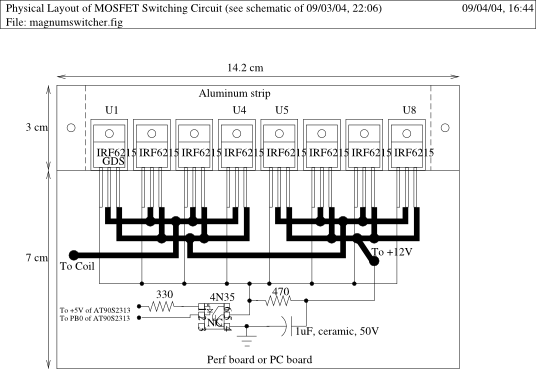 |
| Figure 9: Physical layout of the MOSFETs. |
Because of the large currents, the MOSFET switching circuit is not implemented on a printed circuit board, but is constructed on a perfboard with wires connecting components. The thick wires shown in Fig. 9 carry the approximately 10 amps of current, so there we use a heavier 12 AWG stranded wire. Of course the wires from the power supply to the MOSFET circuit also need to be a heavier 12 AWG. The thinner wires between the gates of the MOSFETs and the optocoupler (4N35) can be regular breadboard gauge wire.
The thermal pads between the MOSFETs and the aluminum bar not only provide a thermal connection for the MOSFETs but also provide electrical isolation between the MOSFETs and the enclosure. This is necessary because the metal tab, normally used for mounting the MOSFETs, is internally connected to the drain. For this reason, we also use nylon machine screws to mount the MOSFETs.
A number of holes need to be drilled/cut into the enclosure.
Two holes for the binding post on front.
Two holes for the LED’s on front.
Holes for the terminal block on front.
Power entry module on back.
RS232 connector on back.
MOSFETs and aluminum bar on back.
Power supply on bottom.
Note that the microcontroller board has a RS232 connector mounted on it, and that connector is mounted onto the enclosure from the inside. That’s all the microcontroller board needs for mounting, although you should put a rubber bumper underneath the board to prevent it from accidentally shorting out on the enclosure.
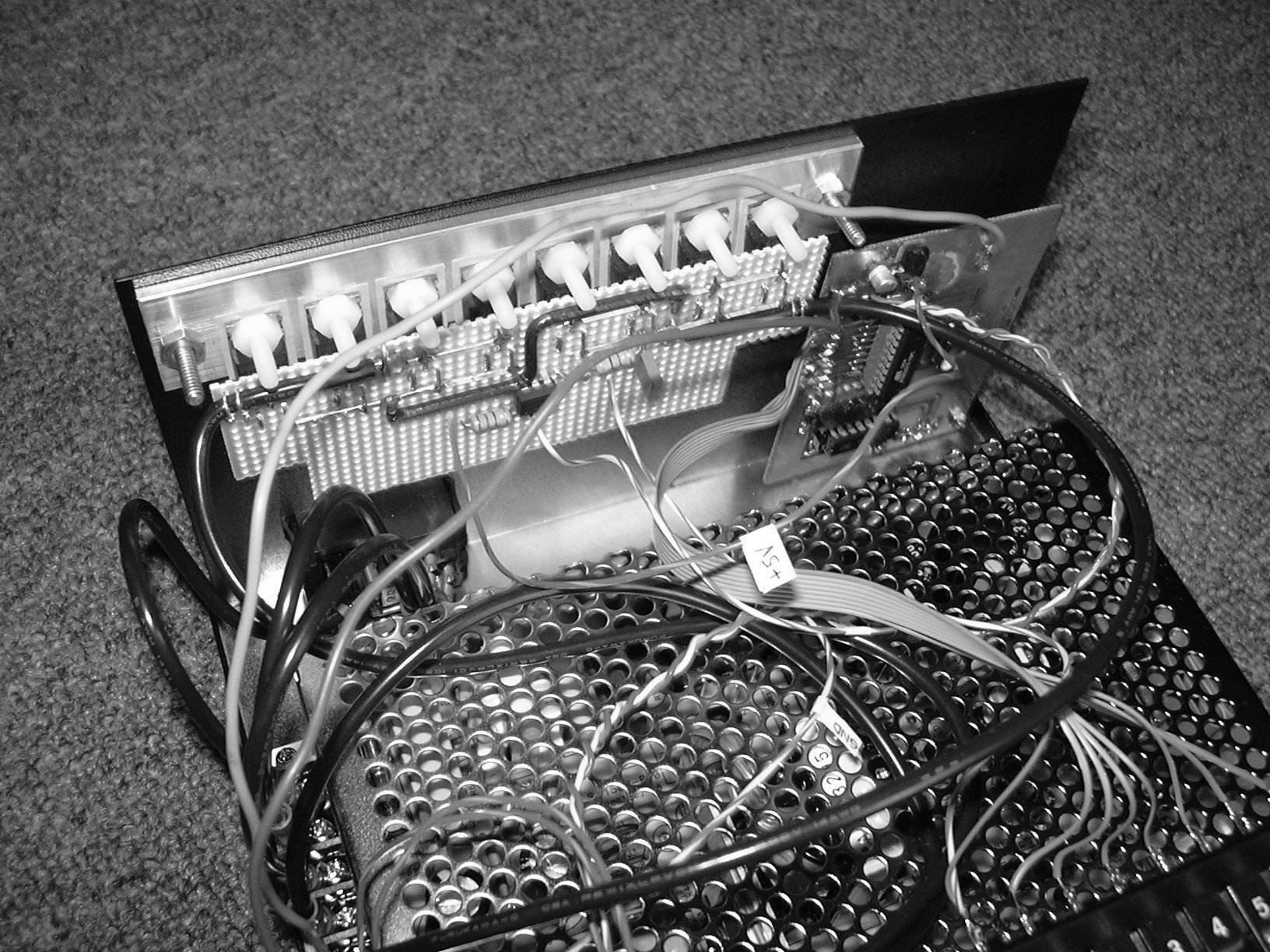 |
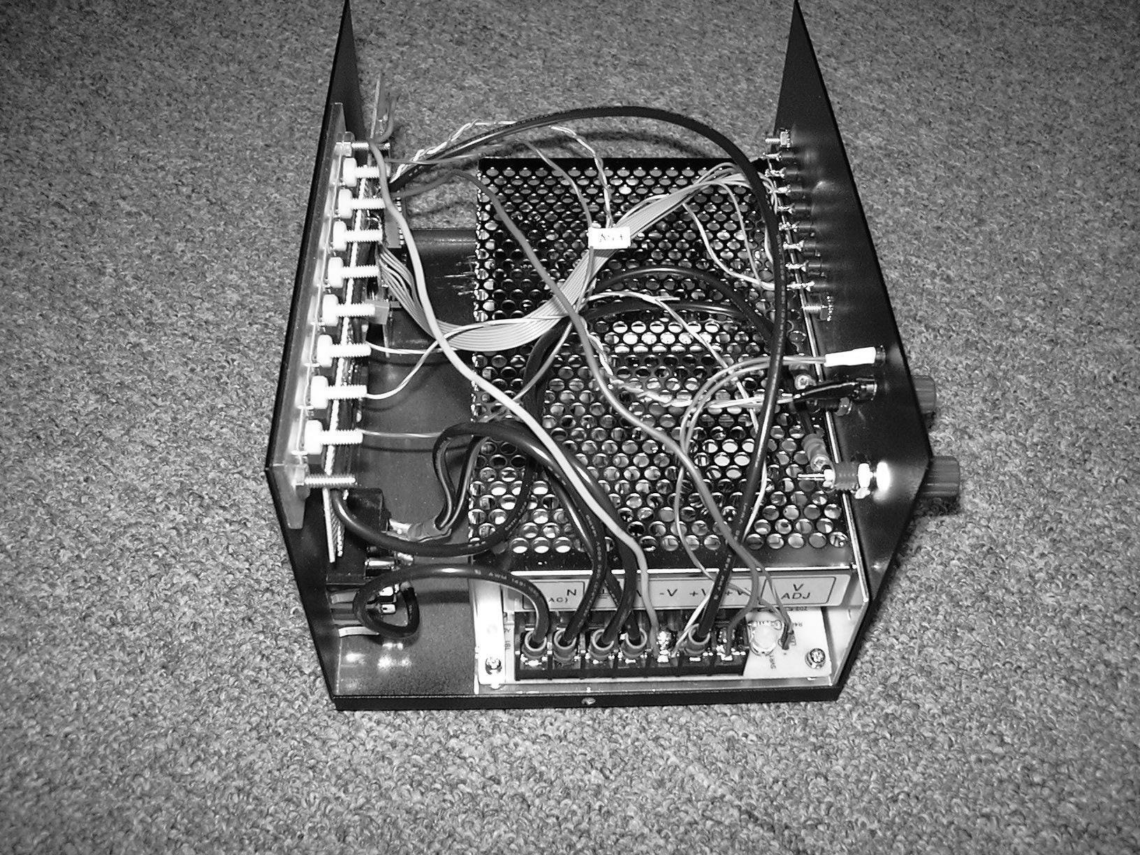
| Figure 10: Inside view of back of pulse controller. |
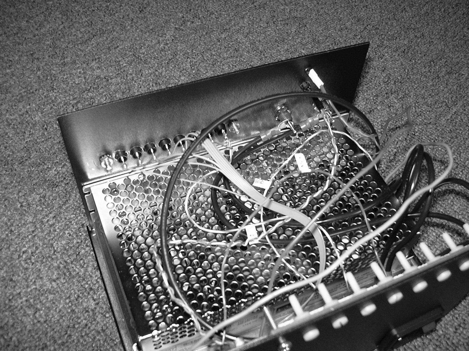 |
| Figure 11: Inside view of front of pulse controller. |
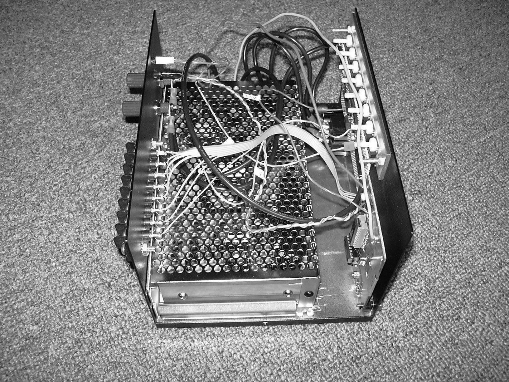 |
| Figure 12: Inside view of right side of pulse controller. |
 |
| Figure 13: Inside view of left side of pulse controller. |
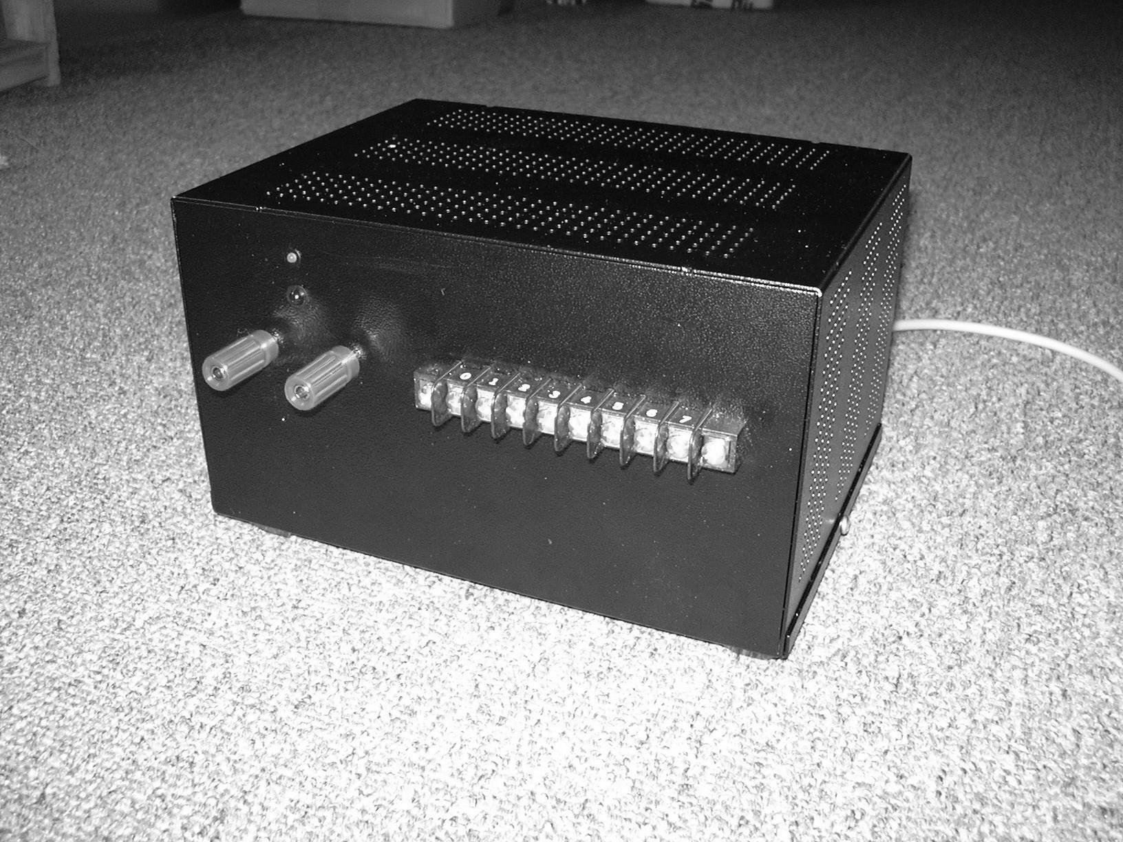 |
| Figure 14: Front view of fully assembled pulse controller. |
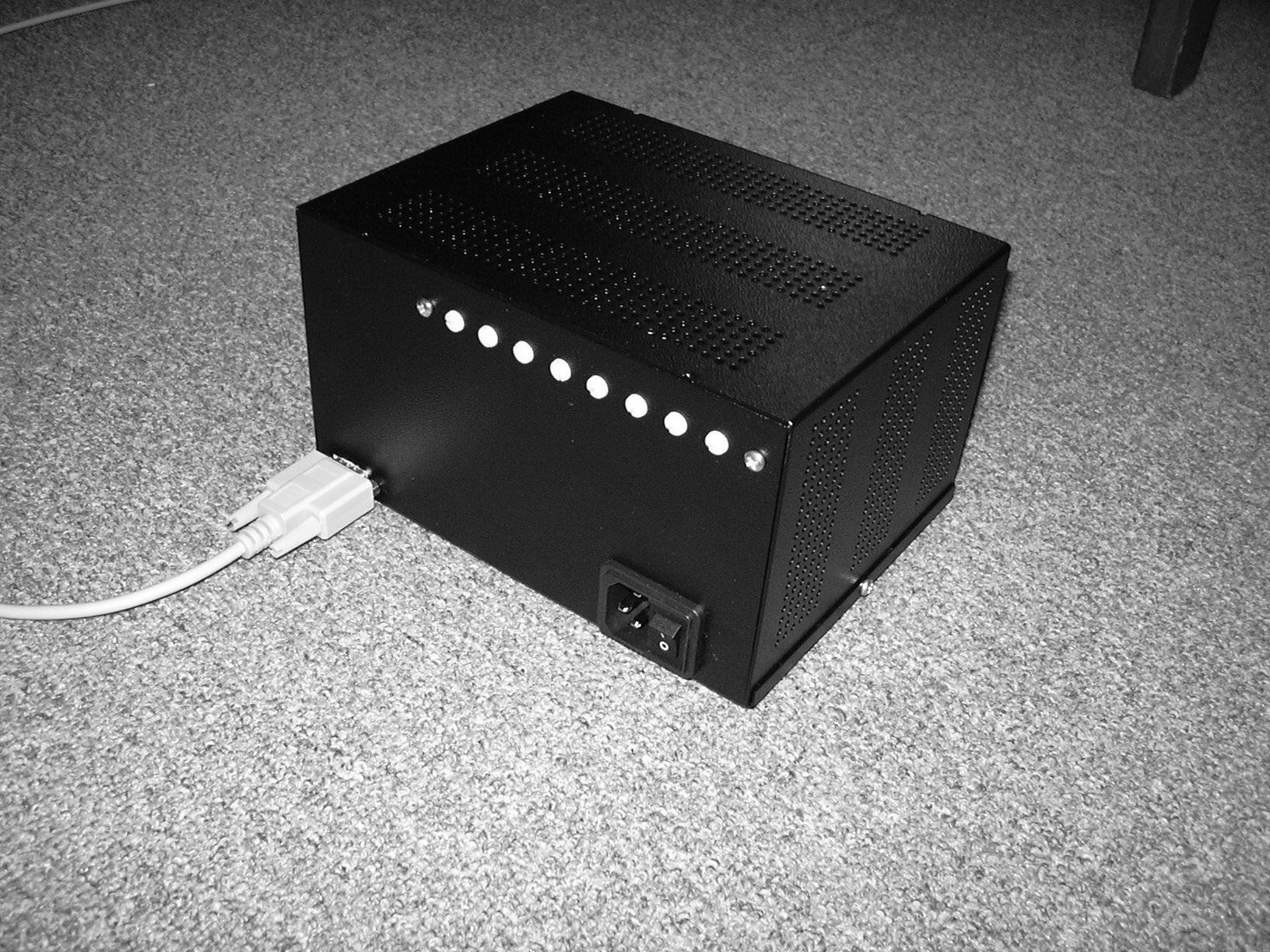 |
| Figure 15: Back view of fully assembled pulse controller. |
3.10 Pulse controller parts list
Meanwell power supply, 12V, 150W
Manuf#S-150-12, 4.5 inch (W) X 8 inch (L) X 2.0 inch (H)
RSI Power $55.70
or
Peak to Peak Power, Stock # 10084 $68.10Enclosure and attachments
DB9 Extension cable, female/female, "straight through", pin connections: 1-5, 2-4, 3-3, 6-9, 7-8.
DB9F-DB9F 3M, Manuf Assmann, Manuf#AK182-3, Digikey#AE1017-ND $6.11
10FT,DB9(F),DB9(F), Manuf#30-9510-77, Mouser#601-30-9510-77, non stock $3.14Enclosure, alum perf 8 inch (L) X 6 inch (W) X 4.5 inch (H)
Mouser#537-PERF146-BT, only black version $27.63
Digikey L180-ND $29.64
Manuf#PERF-146 PL, plain, direct from Manuf. $27.17Power entry module, cutout hole: 26.9 x 39.1 mm
Manuf Corcom/Tyco, Manuf#10CS1, digikey#CCM1647-ND $8.15
Mouser#592-10CS1 $5.83Binding Post, Red, Manuf Johnson Components, Manuf#111-0102-001
Digikey#J164-ND $1.80
Mouser#530-111-0102-1 $1.54Binding Post, Black, Manuf Johnson Components, Manuf#111-0103-001
Digikey#J165-ND $1.80
Mouser#530-111-0103-1 $1.54Molex/Beau Barrier Terminal Blocks .375 PCB 8P SINGLE, Mfr:Molex, Mfr#38720-3208
Mouser#538-38720-3208 $3.39
Digikey#WM5734-ND $5.74LED Panel mounts for 5mm LEDs
Any 1 of these 3:
Mouser#696-SSH-LX5090 3($0.10)
Mouser#696-SSH-LXH501 3($0.10)
Mouser#696-SSH-LX5091 3($0.10)LED Panel mounts for 3mm LEDs
Mouser#696-SSH-LX3050 3($0.10)LED red, 5mm
Digikey#67-1102-ND 3($0.10)4-40 Mounting screws for power supply 4($0.05)
from any hardware storeAmerican Power Cord, Qualtek Electronics, Part#312008-01
Digikey Part#Q352-ND $7.14
or
European Power Cord, Qualtek Electronics, Part#364002-D01
Digikey Part#Q135-ND $6.56
or
Australian Power Cord, Qualtek Electronics, Part#374003-A01
Digikey Part#374003-A01-ND $9.30
Switcher board
Aluminum rectangular bar
5.6 inch (142 mm) long x 1.0 inch (25.4 mm) wide x 1/8 inch (3.175 mm) thick
Available in hobby supply stores where K&S metals are sold (http://www.ksmetals.com).The following machine screws and nuts can be purchased from a hardware store:
Nylon machine screws
#6-32, 1/2 inch length 8($0.18)
Nylon hex nuts
#6-32 8($0.15)
Steel machine screws #6-32, 1/2 inch length 2($0.07)
for MOSFET bar attachment
Steel machine screws #6-32, 3/4 inch length 2($0.07)
for Terminal strip attachment
Steel hex nuts #6-32 4($0.05)IRF6215 MOSFETS, Manuf International Rectifier, Manuf#IRF6215
Digikey#IRF6215-ND 10($1.367)Thermal pads for TO-220 Mouser#532-53-77-9AC 20($0.29)
Aavid Thermalloy Heatsink Hardware THERMALSIL INSULATOROptoisolator 4N35, 6pin dip, Manuf Fairchild, Mouser#512-4N35 $0.30
330 Ohm resistor, axial leaded
Mfr:KOA Speer, Mfr#CF1/4L331J, Mouser#660-CF1/4L331J $0.05470 Ohm resistor, axial leaded
Mfr:KOA Speer, Mfr#CF1/4L471J, Mouser#660-CF1/4L471J $0.051 uF, 50V, axial leaded ceramic cap, Z5U, 20%
Mfr:Kemet, Mfr#C430C105M5U5CA,
Mouser#80-C430C105M5U $0.64Perfboard, epoxy glass 6 inch X 17 inch
Digikey#V1122-ND $16.67
Microcontroller board
Atmel AT90S2313-10PC, onlinecomponents.com 2($5.22)
This part is no longer manufactured by Atmel, but is available at onlinecomponents.com. Atmel’s replacement for this part is ATtiny2313, Mouser# 556-ATTINY2313V10PU. The pinout is the same. There are some differences which Atmel discusses in their application note, Replacing AT90S2313 by ATtiny2313.DIP socket, 20pin
Mouser#517-4820-3004-CP $0.19RS232 Interface IC, DIP package, Mouser#511-ST202EBN 2($1.30)
DIP socket, 16pin
Mouser#517-4816-3004-CP $0.165V, 0.1A voltage reg, 78L05, TO-92, Mfr:STMicro, Mfr#L78L05ABZ
Mouser#511-L78L05ABZ $0.28NPN 2N3906 SMD, Mouser#MMBT3906 $0.03
10uF electrolytic SMD cap, Mfr:Nichicon,
Mfr#UWX1E100MCL1GB
Mouser#647-UWX1E100MCL1 $0.1722pF radial leaded cap, Mfr:Vishay/Sprague,
Mfr#1C10C0G220J050B
Mouser#75-1C10C0G220J050B 2($0.21)220 Ohm SMD resistor, Mfr:Xicon, Mfr#260-220
Mouser#260-220 $0.080.1uF, 50V, SMD ceramic capacitor, Mfr#699-CL21E104MBNC
Mouser#699-CL21E104MBNC 4($0.058)1uF, 50V, SMD ceramic capacitor, Mfr:AVX,
Mfr#12065G105ZAT2A
Mouser#581-12065G105Z $0.66CONN DB9 MALE SOLDER CUP TIN, Manuf:Norcomp, Manuf#171-009-102-021
Digikey#2209M-ND $1.571 PCB (3" X 7.5") from Advanced Circuits (4pcb.com) $33.00
This PCB combines microcontroller board and amplifier which needs to be cut in two.
1 Descriptions of current flow are in terms of conventional current. This means that positive current flows from a high potential to a lower potential. This is opposite to the flow of electrons which always move from a low potential to a high potential.
2 The on-resistance is a function of the gate to source voltage, the current through the device, and the temperature. The value of 0.3 ohms is typical of the way the IRF6215 is used in the Magnum. It is important to keep in mind however, that the on-resistance will increase as the temperature of the device increases. When the on-resistance increases the current delivered to the polarization coil will decrease. If the temperature of the device increases substantialy it could lead to a significant decrease in the polarization of the protons and loss of precession signal strength. Keep this in mind when you are using a sequence of long polarization pulses.
3 Due to tolerances of circuit components all figures that we give are approximate. To find the actual amount of polarization coil current or any other figure that we give in this book, you will have to measure it.