Sensor Coil
The purpose of the sensor coil is to acquire the proton precession signal from the sample, and to provide the amplifier with as much of the signal as possible.
4.1 Sensor coil requirements
Easy access
We use a solenoid geometry for the sensor coil. While other geometries such as a toroid, might be used, the solenoid allows easy access to and quick replacement of the sample.
Low noise
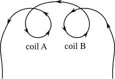
A major problem that needs to be considered in designing a sensor coil is environmental noise. The world is awash in unwanted man-made magnetic field fluctuations, and a solenoidal coil will pick up some of this. In fact the traditional AM radio antenna is just a solenoidal coil wound on a ferrite rod. The way we mitigate this problem is to use two identical sensor coils.
The two coils are wound in opposite directions with respect to each other and connected in series. They are mounted parallel to each other so that external magnetic field noise common to both coils is cancelled out. The signal from the sample in one of the coils can then be detected with minimal interference. Both coils are large enough to accomodate a 2.0 ounce (59 ml) bottle containing the sample.
This implies that to get a signal, you must place a sample bottle into only one of the sample coils. If you were to place a bottle in each sample coil, then a signal would be produced in each coil, and the two signals would exactly cancel each other out, resulting in no signal at all.
No ferromagnetic or metallic materials nearby
The magnetometer is designed to operate using the Earth’s magnetic field. The coils must therefore be placed in a position where there is minimal disturbance of the field. This usually means placing the coils outdoors away from any structures containing ferromagnetic materials and away from any power lines or other sources of electromagnetic interference. The coils may be operated indoors as long as it can be verified that the magnetic field is uniform. Any non-uniformity in the field will cause the resulting signal to be degraded.
When placed outside, we recommend that the coils not be put directly on the ground, since ferromagnetic rocks and other materials in the soil may cause small localized distortions of the Earth’s magnetic field. A wooden or plastic stand (no nails, screws, or fasteners) is suitable for placing the coils on.
Large metallic objects that are not ferromagnetic, such as aluminum, copper, and brass, should also be kept away from the coils. This is because they can induce eddy currents when the current in the polarization coil is turned off, corrupting the magnetic field in the region of the sample. Of course, this also means that attempting to shield the coils from magnetic noise by placing them in a metallic box will guarantee that no proton precession signal is detected.
Wire size, Johnson noise, and Q
The wire size used, to create the sensor coils, is an important parameter. On the one hand, you want thin wire because the more turns you have, the stronger the signal. On the other hand, you want fat wire so that the Johnson noise is low, and the quality factor (Q) is high. Johnson noise is thermal noise, and is higher for larger resistance. The Q is a measure of how ideal an inductor is, and is lower for larger resistance. We have chosen 22 AWG solid copper magnet wire. This size is a suitable fit for the constraints.
4.2 How the coils are wired together
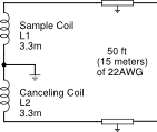
It’s important to wire the two coils together correctly. If wired incorrectly, the ambient noise will not be diminished, but amplified. The two coils are wound in opposite directions with respect to each other and connected in series as shown in figure 16.
 |
| Figure 16: How to connect the two coils together. |
Before permanently wiring them together, it’s a good idea to first temporarily connect them as you think they should go, then check with an oscilloscope whether they do indeed diminish environmental noise. One way to do this is, is to place the two coils inside the polarizing coil, then connect the polarizing coil to a signal generator. If connected correctly, this signal will be greatly reduced when viewing the output of the connected coils with an oscilloscope.
4.3 How to connect cable to coils
The sample coils are connected to the amplifier via a two conductor 22 AWG shielded cable. Figure 17 below indicates how the cable is connected to the coils.
 |
| Figure 17: How to connect a shielded cable to the coils. |
The cable shielding is connected to the ground of the amplifier, as well as the center of the two coils. The two conductors of the cable are connected to opposite ends of the coils.
4.4 Specifications of sensor coil
22 AWG solid copper wire, wire diameter(w/o insulation) = 0.643 mm
coil inner diameter = 3.8 cm
coil length = 10.0 cm
number of wire layers = 4
turns/layer = 138, total number of turns = 552
Approximate inductance = 3.5 mH
Approximate resistance (with 15 meters of line) = 5.9 Ohm
4.5 Sensor coils parts list
2 Acrylic tubes, 1.5 inch (3.81 cm) outer diameter, 4 inch (10.16 cm) long, 1/16 inch (0.0625 cm) thick, 1.375 inch (3.493 cm) inner diameter.
Acrylic disk, 4.25 inch diameter, left over from polarizing coil, cut in half.
2 Acrylic rings, 1.7875 inch (4.54 cm) outer diameter, 1.4375 inch (3.65 cm) inner diameter, 5/32 inch (0.397 cm) thick.
22 AWG solid copper magnet wire, 520 feet (158.5 meter) (260 feet for each coil).
2 conductor shielded 22 AWG cable, 50 feet (15.2 meter).
Spade terminals #6 for 22-18 AWG wire, Qty 3, Mouser Part#538-19131-0031.
Plastic bottles, 2oz, translucent HDPE cylinders,
at sunburstbottle.com, or specialtybottle.com.
4.6 Construction of sensor coils
In constructing the sensor coils, it is important to keep in mind that the more identical the two coils are, the better they will be at canceling environmental noise. Especially, the total number of turns should be the same. One way to check how similar the coils are, is to weigh the coil forms before they are wound, then weigh them after.
Steps for constructing the sensor coils:
Cut the acrylic to the dimensions given in the parts list.
Using an acrylic solvent, glue the coil parts together as shown in figure 3. Ensure that the sample bottle can slide into the top of at least one of the coils (the rings on the top of the tube should not get in the way of the bottle).
Weigh the two coil forms.
Wind the coils in opposite directions using 22 AWG copper magnet wire. See figure 16 above.
Weigh the two coils.
Compare the weight differences between the wound coil and empty coil forms. As necessary, remove wire loops to make the weight differences as identical as possible.
Use quick drying epoxy applied to the ends of the coil to prevent the windings from coming undone.
Wire the coils together so that they cancel environmental noise. See section "How the two coils are wired together".
Epoxy the two coils together at their base, as shown in figure 4, making sure the two coils are parallel to each other.
Using a scrap piece of flat acrylic, epoxy on a stabilizer (ensures that the sample coils maintain a fixed position as the polarizing coil is tilted) as shown in figure 20.
Put more epoxy around the coils as needed to make them more mechanically stable.
Attach the 2 conductor shielded cable as described in section 4.3.
Attach the spade terminals to the cable.
 |
| Figure 18: Sample coil forms. |
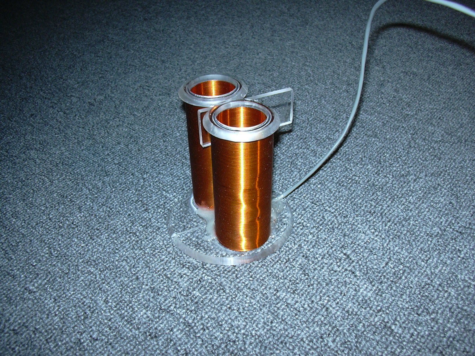
 |
| Figure 19: Wound sample coils with sample bottle. |
 |
| Figure 20: Sample coils with stabilizer. |
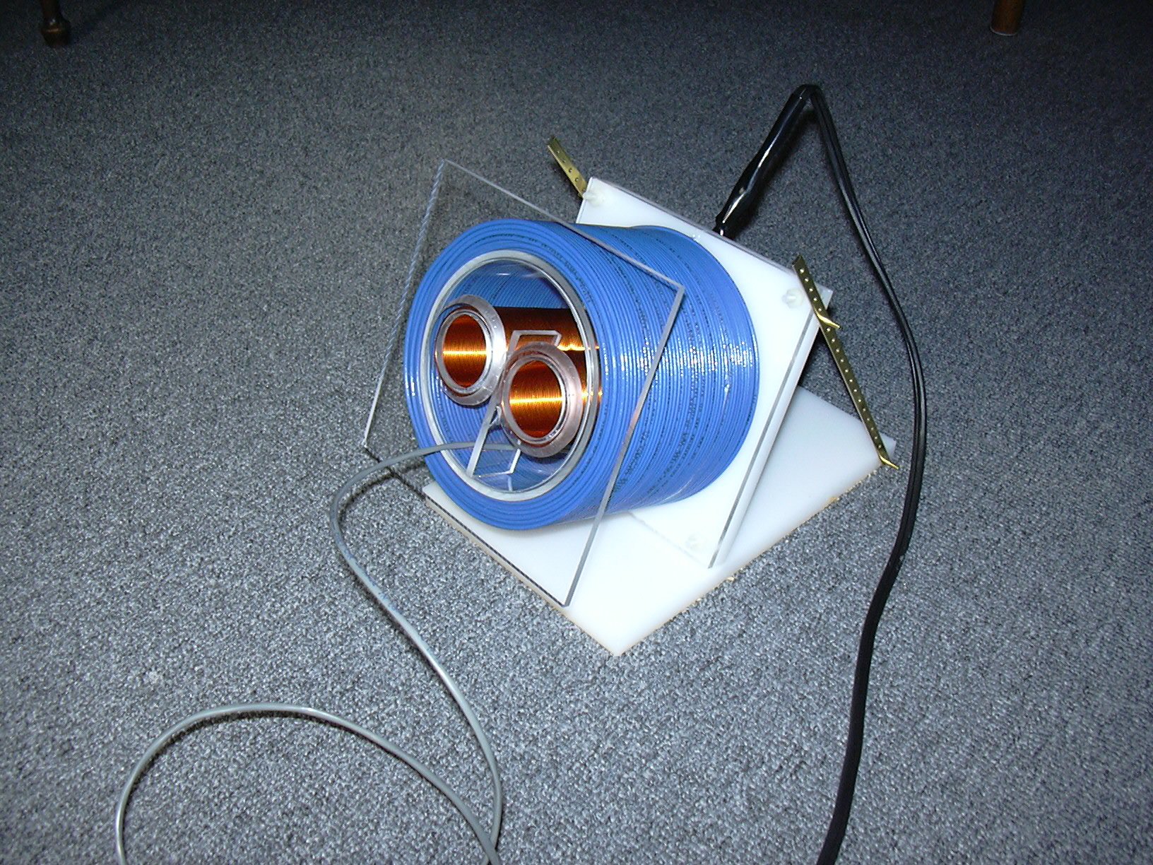 |
| Figure 21: Polarizing coil with sample coils inside, on tiltable platform. |